|
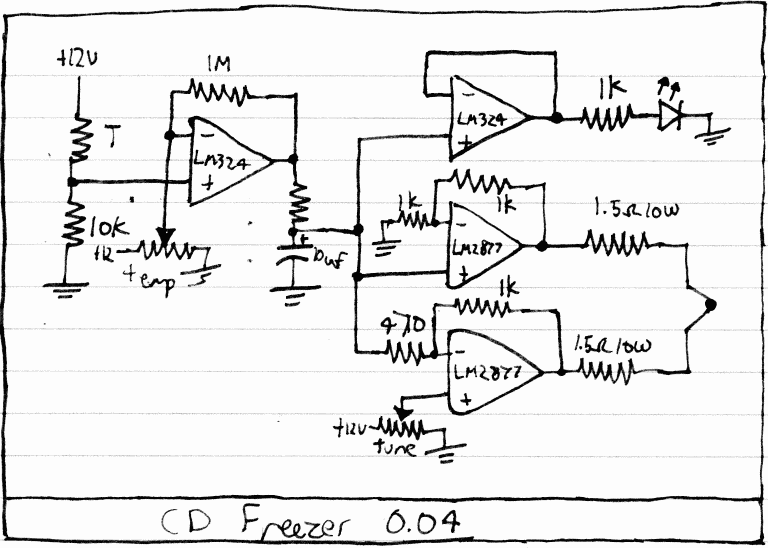
This is a modification of 0.03. It
adds a simple RC filter to help damp some oscillation, and lower(1.5
ohm 10-watt) output resistors to let it drive more power. The
circuit diagram to the left is nearly exactly how my prototype
is, except I've put a diode in the way of the peltier so it
doesn't try and heat the peltier in case I hook anything up
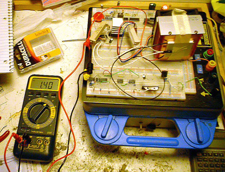
backwards. Check out the picture of the working prototype! Don't be alarmed, most of the stuff on the board is old stuff that's not currently being used... see the area with the two power resistors, the big heatsinked chip, and the peltier device on the heatsink with fan? That's the right place. The multimeter shows 1.40v over 1.5 ohms for nearly exactly 1 amp of current! This is the maximum current before the LM1877 and LM2877 start current limiting, so to increase power I'll need to increase the voltage supply. I think plain 12v ought to be good enough, but we'll see. The chip and resistors get warm, but not hot. Technically I could leave the resistors out since the chip limits for me, but that would mean that the amplifier would have to dissipate an extra 5 watts of heat or so. Not a good plan. The red spot to the left of the leftmost power resistor is the LED, which glows brightly during cooling, glows dimly when just right, and turns off when it's overshot. The circuit is pretty much as I want it, but a few improvements have occurred to me, like driving the thermistor from a voltage reference instead of supply power for higher precision and less noise, and better damping for less oscillation and overshoot. There will probably be a 0.05 built, and from there, I plan to build 1.00. |