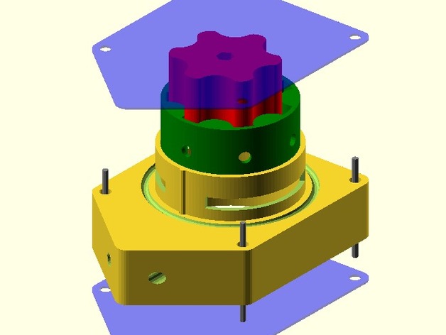
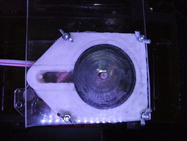
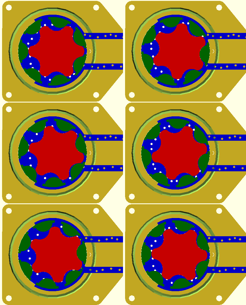
A 3d-printable rotary displacement pump modelled in OpenSCAD.


It is extremely satisfying to post a pump that works! Greased up, this pump can actually generate PRESSURE enough to squirt through some feet of aquarium tubing. It still doesn't do vaccuum suction, but neither do industrial hydraulic pumps of this design, so c'est la vie.
 Name                           Last modified      Size  Description Parent Directory                                    -
 mk6-valve-sleeve.stl           2016-02-23 09:19  402K  Valve Sleeve
 gerotor-mk6.scad               2016-02-23 09:19  9.2K  Source code, requires util.scad
 mk6-outer.stl                  2016-02-23 09:19  462K  Outer Rotor
 mk6-case.stl                   2016-02-23 09:19  1.2M  Main Body
 Gerotor_Modeling_with_NX3.pdf  2016-02-23 09:19  1.2M  Magic formula for gerotor shape
 mk6-inner.stl                  2016-02-23 09:19  219K  Inner Rotor
 images/                        2016-02-23 09:19    -   Image Pile
 util.scad                      2017-09-12 19:53  8.8K
 80mm-casefan-dimensions.jpg    2013-05-03 06:48   45K
There are four parts to print: inner rotor, outer rotor, valve sleeve, and case. The inner and outer rotors print slightly too tall, so you can sand their rough printed tops smooth. I did not acetone-polish mine, but it couldn't hurt.
The top and bottom are 80mm squares of acrylic or plexiglass sheet with 1/8" corner holes drilled in a 71.5mm square (exactly like an 80mm case fan). The flat plastic sheet makes a better seal than a printed bottom and lets you spot any leaks easily. One hole in the center is needed to drive the input, and it is not centered - it is 3.5mm off center.
Fish-tank silicone, and four long thin 6-32 screws and nuts hold the pump together.
A 1/4" hex screwdriver bit or allen wrench can turn it.
The gerotor is generated programmatically and can easily be adapted to other needs. It follows the equations and measurements shown in the above PDF. The SCAD version adds a function to distribute points more evenly, otherwise the model would have 100 points in the troughs and 3 at the tops!